Connecting Sparkfun ESP32 Board and CCS811/BME280 Environmental Sensor with IoT Ensemble
In this tutorial, we will be taking a generic ESP32 board, connecting a simple environment sensor, and send messages with IoT Ensemble. For simplicity sake, I have chosen to use Sparkfun's "Qwiic" connect ecosystem, which is a plug-and-play method of connecting boards and sensors.
Things you will need
- SparkFun Thing Plus - ESP32 WROOM Board (You may also use a different generic ESP32 board, but it won't use the Qwiic system)
- A Qwiic Cable (Any length is fine for this tutorial)
- Your computer/laptop
- A Micro-USB cable to connect the ESP32 to your computer
- SparkFun Environmental Combo Breakout - CCS811/BME280 (Again, you may choose to use a more generic version of this sensor, but it won't use the Qwiic system)
- Arduino IDE installed on your computer
- A Fathym IoT Ensemble account (we’re using the free, shared version)
Part 1 - Hook Up Your Hardware
First, we need to attach the sensor to your board. Take the qwiic cable, and plug it into the ESP32 "Qwiic" port. Take the other end of the cable, and plug it into either of the two "Qwiic" ports on the Environmental Sensor. Your hardware is ready to go!
Part 2 - Installing Arduino IDE and Necessary Software
Next, we will need to install all of the required software/libraries on your computer
Installing Arduino IDE
Download your version of Arudino IDE here. Follow all of the steps in the wizard to complete installation (You can keep all of the default options the same)
Add Sensor Libraries
Once that is complete, we need to install some libraries. Click the following links to download each zip folder
Download the BME280 Library (ZIP)
Download the CCS811 Library (ZIP)
Once you have downloaded those, go to your Arduino IDE screen. In the top toolbar, select Sketch -> Include Library -> Add .ZIP Library, as shown below:
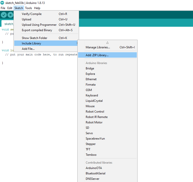
This will open a file browser. Navigate to your downloaded package, select the zip folder, and click "Open". Repeat this step for the second package.
Add Additional Library
In the top toolbar navigate to Tools -> Manage Libraries. On the next screen, type "NTPClient" into the search bar. A library with the same name should show up in the list. Click "Install", and then "Close"
Add ESP32 Board Definition
In order for us to work with the ESP32, we need to add a board "definition".
Copy the following link:
Back in your Arduino IDE, in the top toolbar, click File -> Preferences. You will be taken to the follow screen:
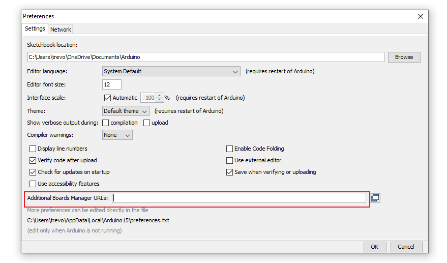
Take the link from the previous step, and paste it into the "Additional Boards Manager URLs" field (highlighted above in red). Click "OK"
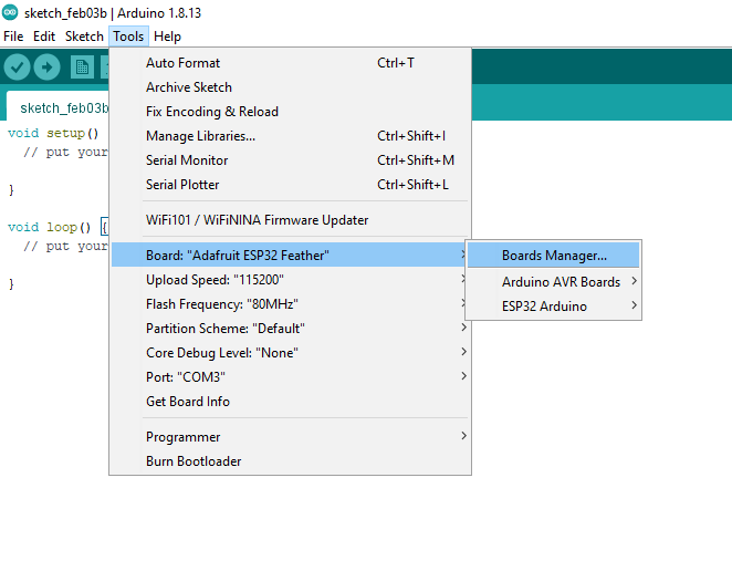
- Next, in the top toolbar, click Tools -> Board: "Name of Board" -> Boards Manager..., as shown below:
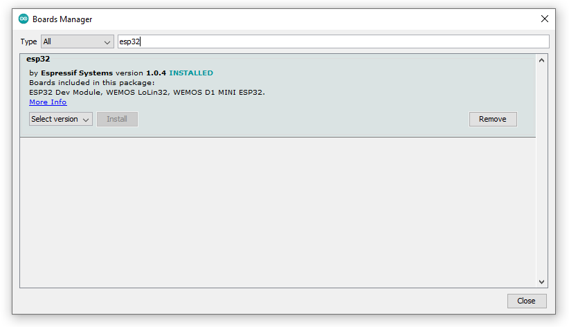
In the next screen, type "esp32" into the search bar. A board definition with the same name will appear, click "Install", then click "Close" (as shown below)
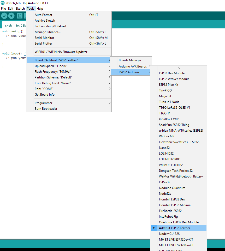
- Next, navigate to Tools -> Board: "Name of Board" -> ESP32 Arduino and select Adafruit ESP32 Feather, as shown below:
Determine Communication Port Number
Now that we have all the necessary libraries and dependencies, we need to tell Arduino IDE which port to use to communicate with your ESP32.
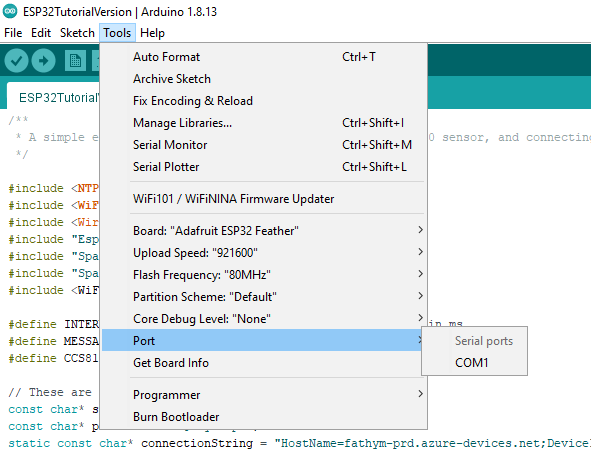
- Before plugging in the ESP32 to your computer, click Tools -> Port in the top toolbar of Arduino IDE. This will display a list of ports that are currently being used. Generally, there will only be one or two ports listed, depending on what you have plugged into your computer. Take note of the ports in this list. The picture below shows a list of ports before the ESP32 board is plugged in.
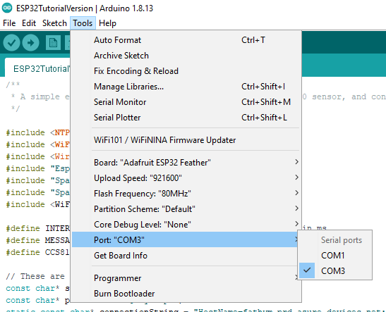
- Next, plug your ESP32 board directly into one of your computer's USB ports. After this, follow the previous step to view the list of available ports. You should now see an additional port that wasn't in the list before. This is the port that your ESP32 board is using. Click the port to select it. In the picture below, "COM3" is the port that is new in the list.
Get Code Onto your ESP32 board
Now that your Arduino can talk to your ESP32, it's time to put some code on your board!
First, copy the following code:
/**
 * A simple example using an ESP32 board with a CCS811/BME280 sensor, and connecting to the cloud with Iot Ensemble
 */

#include <NTPClient.h>
#include <WiFi.h>
#include <Wire.h>
#include "Esp32MQTTClient.h"
#include "SparkFunBME280.h"
#include "SparkFunCCS811.h"
#include <WiFiUdp.h>

#define INTERVAL 30000 //Time interval for sending messages in ms
#define MESSAGE_MAX_LEN 512
#define CCS811_ADDR 0x5B

// These are the four values that need to be filled out. NOTE: ESP32 boards can only connect to 2.4GHz networks, they can NOT connect to 5Ghz networks///////
const char* ssid     = "Your Wifi Name (SSID)";
const char* password = "Your Wifi Password";
static const char* connectionString = "Your Connection String";
char DeviceID[] = "Your DeviceID";
//////////////////////////////////////////////////////////////

char deviceVersion[] = "0.0.1";
char deviceType[] = "ESP32";
char latitude[] = "40.7578";
char longitude[] = "-104.9733";
const char *messageData = "{\"DeviceID\":\"%s\", \"DeviceType\":\"%s\", \"Version\":\"%s\", \"DeviceData\": {\"Latitude\":%s, \"Longitude\":%s}, \"SensorReadings\": {\"Temperature\":%f, \"Humidity\":%f, \"TVOC\":%d, \"CO2\":%d, \"Pressure\":%f, \"Altitude\":%f}, \"SensorMetadata\": {\"_\": {\"SignalStrength\": 1}}}";
static bool hasIoTHub = false;
static bool hasWifi = false;
int messageCount = 1;
static bool messageSending = true;
static uint64_t send_interval_ms;

//Global variables obtained from the two sensors
unsigned int tVOC = 0;
unsigned int CO2 = 0;
float tempf = 0;
float humidity = 0;
float pressureInHg = 0;
float altitudeFt = 0;

CCS811 myCCS811(CCS811_ADDR);
BME280 myBME280; //Global sensor object for BME280
WiFiUDP ntpUDP;
NTPClient timeClient(ntpUDP);

static void SendConfirmationCallback(IOTHUB_CLIENT_CONFIRMATION_RESULT result)
{
  if (result == IOTHUB_CLIENT_CONFIRMATION_OK)
  {
    Serial.println("Send Confirmation Callback finished.");
  }
}

static void MessageCallback(const char* payLoad, int size)
{
  Serial.println("Message callback:");
  Serial.println(payLoad);
}

static void DeviceTwinCallback(DEVICE_TWIN_UPDATE_STATE updateState, const unsigned char *payLoad, int size)
{
  char *temp = (char *)malloc(size + 1);
  if (temp == NULL)
  {
    return;
  }
  memcpy(temp, payLoad, size);
  temp[size] = '\0';
  // Display Twin message.
  Serial.println(temp);
  free(temp);
}

static int  DeviceMethodCallback(const char *methodName, const unsigned char *payload, int size, unsigned char **response, int *response_size)
{
  LogInfo("Try to invoke method %s", methodName);
  const char *responseMessage = "\"Successfully invoke device method\"";
  int result = 200;

  if (strcmp(methodName, "start") == 0)
  {
    LogInfo("Start sending temperature and humidity data");
    messageSending = true;
  }
  else if (strcmp(methodName, "stop") == 0)
  {
    LogInfo("Stop sending temperature and humidity data");
    messageSending = false;
  }
  else
  {
    LogInfo("No method %s found", methodName);
    responseMessage = "\"No method found\"";
    result = 404;
  }

  *response_size = strlen(responseMessage) + 1;
  *response = (unsigned char *)strdup(responseMessage);

  return result;
}

void setup() {
  Serial.begin(9600);
  Serial.println("ESP32 Device");
  Serial.println("CCS811+BME280 Read Example");

  Wire.begin();//initialize I2C bus

  Serial.println("Initializing...");
  Serial.println(" > WiFi");
  Serial.println("Starting connecting WiFi.");

  delay(10);
  WiFi.mode(WIFI_AP);
  WiFi.begin(ssid, password);
  while (WiFi.status() != WL_CONNECTED) {
    delay(500);
    Serial.print(".");
    hasWifi = false;
  }
  hasWifi = true;

  Serial.println("WiFi connected");
  Serial.println("IP address: ");
  Serial.println(WiFi.localIP());

  Serial.println(" > NTPClient");
  timeClient.begin();
  timeClient.update();

  Serial.println(" > IoT Hub");
  if (!Esp32MQTTClient_Init((const uint8_t*)connectionString, true))
  {
    hasIoTHub = false;
    Serial.println("Initializing IoT hub failed.");
    return;
  }
  hasIoTHub = true;

  myCCS811.begin();

  //Setup the BME280 for basic readings
  myBME280.settings.commInterface = I2C_MODE;
  myBME280.setI2CAddress(0x77);
  myBME280.settings.runMode = 3; //  3, Normal mode
  myBME280.settings.tStandby = 0; //  0, 0.5ms
  myBME280.settings.filter = 0; //  0, filter off
  myBME280.settings.tempOverSample = 1;
  myBME280.settings.pressOverSample = 1;
  myBME280.settings.humidOverSample = 1;

  delay(10); //Give BME280 time to come on

  //Calling .begin() causes the settings to be loaded
  byte id = myBME280.begin(); //Returns ID of 0x60 if successful
  if (id != 0x60)
  {
    Serial.println("Problem with BME280");
  }
  else
  {
    Serial.println("BME280 online");
  }

  Esp32MQTTClient_SetSendConfirmationCallback(SendConfirmationCallback);
  Esp32MQTTClient_SetMessageCallback(MessageCallback);
  Esp32MQTTClient_SetDeviceTwinCallback(DeviceTwinCallback);
  Esp32MQTTClient_SetDeviceMethodCallback(DeviceMethodCallback);
  Serial.println("Start sending events.");
  randomSeed(analogRead(0));
  send_interval_ms = millis();

}

void loop() {
if (hasWifi && hasIoTHub)
  {
    if (messageSending &&
        (int)(millis() - send_interval_ms) >= INTERVAL)
    {
      timeClient.update();

      myCCS811.readAlgorithmResults(); //Read latest from CCS811 and update tVOC and CO2 variables

      char messagePayload[MESSAGE_MAX_LEN];

      tempf = myBME280.readTempF();
      humidity = myBME280.readFloatHumidity();
      altitudeFt = myBME280.readFloatAltitudeFeet();
      pressureInHg = myBME280.readFloatPressure();
      tVOC = myCCS811.getTVOC();
      CO2 = myCCS811.getCO2();

      snprintf(messagePayload, MESSAGE_MAX_LEN, messageData, DeviceID, deviceType, deviceVersion, latitude, longitude, tempf, humidity, tVOC, CO2, pressureInHg, altitudeFt);
      Serial.println(messagePayload);
      EVENT_INSTANCE* message = Esp32MQTTClient_Event_Generate(messagePayload, MESSAGE);
      Esp32MQTTClient_SendEventInstance(message);
      send_interval_ms = millis();
    }
    else
    {
      Esp32MQTTClient_Check();
    }
  }
  delay(10);
}
Next, in the ArduinoIDE, delete the existing template code. Then, paste the code you just copied.
Before we can continue, we need to register your ESP32 device with Iot Ensemble
Part 5 - Configuring IoT Ensemble
Before we can tell your device where to send data, we first need somewhere to send the data. There are a number of different ways this can be accomplished, with IoT Ensemble the focus is helping you leverage best practice cloud IoT technology. Here we'll be using the Azure IoT Hub to connect devices to a shared data flow, and then make it avaiable downstream for use in other applications.
Follow these steps to create a new device in IoT Ensemble. For more details on the full IoT Ensemble experience, check out our full documentation.
Start by navigating to the IoT Ensemble Dashboard and sign in or sign up. For the purposes of moving forward, you will only need the Free license and no credit card will be required.
Enroll a Device
In the Connected Devices section, click the Enroll New Device button, provide a name for your device (i.e. my-first-device) and click Enroll Device. That’s it! Your device is now registered and should be visible in the dashboard, along with its associated connection string.
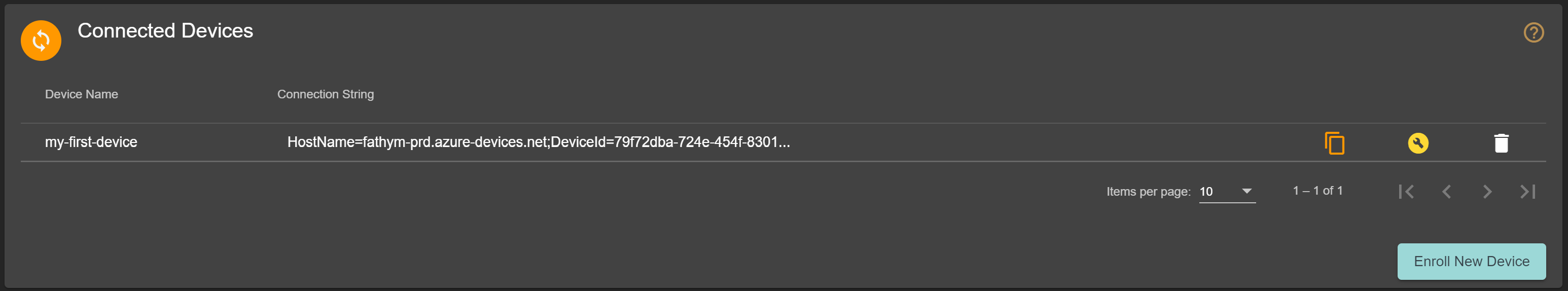
Click on the ![]() button to copy your connection string to your clipboard. Your connection string should look something like this:
button to copy your connection string to your clipboard. Your connection string should look something like this:
HostName=YourHostName;DeviceId=YourDeviceID;SharedAccessKey=YourDeviceKey
In addition to the whole connection string, there is one key part that we need: the YourDeviceID portion. This value needs to be a part of the data payload. Let's add them now.
Configure the Code
Back in the Arduino IDE, near the top of the code, your should see a section of four values that need to be filled in, like this:
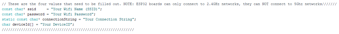
First, fill in the WiFi name and password of the network you plan on using.
Please Note!
With this particular ESP32 board, it can only connect to 2.4 Ghz Wifi networks. The board CAN NOT connect to 5 Ghz networks. If you attempt to connect to a 5 Ghz network, this code will not work.
Next, take your connection string from Iot Ensemble, and paste it into the "connectionString" variable.
Finally, take the YourDeviceID portion of your connection string, and paste it into the "DeviceID" variable. Save your code file.
Verify and Upload Your Code
Now it is time to bring your ESP32 to life! In the top left corner of the Arduino IDE, click the "Verify" button, which looks like a checkbox (shown below)
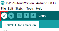
This will compile your code, and ensure that your code has no errors like missing libraries or incorrect syntax.
Once this is complete, click on the "Upload" button, which looks like a horizontal arrow, and is right next to the "Verify" button (shown below)
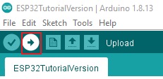
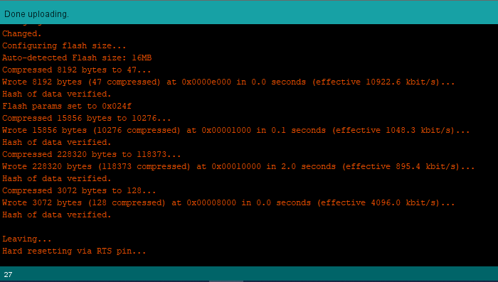
This will take your code, and flash it to the ESP32 board. You will see some red text outputted to the terminal on the bottom of the screen. The toolbar will say "Done Uploading" once complete, and should look something like this:
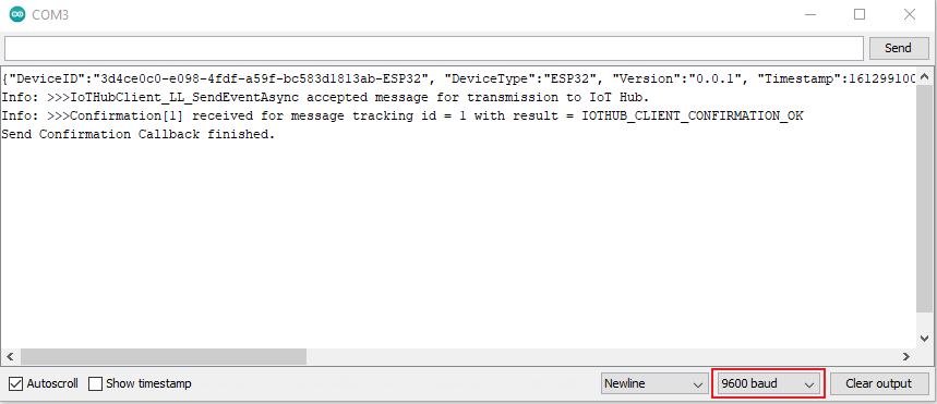
Your ESP32 should now be taking sensor readings, and sending the information up to Iot Ensemble! If you want to see a live view of your code running, click Tools -> Serial Monitor in the top toolbar. You should be able to see your sensor readings every 30 seconds. In the Serial Monitor window, make sure that you have the baud rate set to "9600", as shown below:
Once you confirm that messages are sending correctly, you can now go to IoT Ensemble and see your messages in real time. Messages will appear under the "Device Telemetry" section, as shown below:
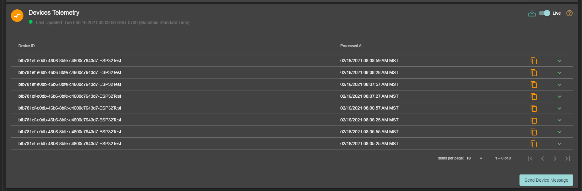
Just make sure that you have the Device Telemetry toggle set to "Enabled". For more information on Device Telemetry, check out our docs.
Next Steps
Hooking up the hardware is just the beginning of Iot Ensemble. There are a number of options for accessing and displaying your data easily.
- Connecting Downstream Devices will walk through the different ways to access your data.
- Check out the documentation for connecting your data with outside tools, such as Power BI, Grafana, and others.